
One USB line feeds the Arduino Mega2560Ħ.Audio runs from a 3.5mm connector to the RCA jacks on the sega amp board.The VGA is connected to the adapter board.I put a standard PC in the place the original board cage was located at. 11p (1x11) for sending commands to the drive board.ĥ.26p (2x13) for the pedals and wheel pot.50p (2x25) for buttons, lamps, shifter.This line usually powers the I/O board inside the cage, but I will use it to provide power to the drive board instead. I built an adapter board which provides several connectors for the original cabling: I disconnected all cables on the sega power supply (1x AC, 1x Main Power, 1x Aux Power) and pluged in a handmade power cord for the PC instead.Ĥ. As the PC will generate the sounds, I disconnected the power cables going to the sound board (1 connector) and audio cables (2 pairs of connectors) from the amp board and pluged in a standard pc audio cable in there.ģ. Then I "moved" the cables going to the back of the base to the center.Ģ. I removed the CPU Board cage by unpluging all the connectors and removing two screws that hold the cage in place. None of the original wiring was cut/modified, so I can put a real Boardset back in there at any time.īig ThankYou goes to BigPanik for the initial idea and "proof of concept" of using an Arduino in the first placeġ. I used an Arduino (MEGA 2560) to interface the PC to the cabinet.

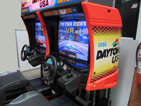
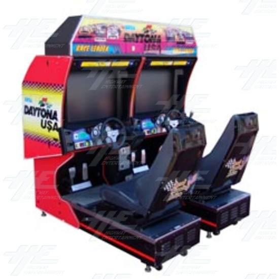
I got bored of my Daytona Boardsets dying over and over again, so I swaped them with PCs. I've started to convert my Daytona USA Twins (actually got 3 of em right now, 4th on the way) to PCs without modifying the original wiring.


 0 kommentar(er)
